Installation manual UuZ Wall readers
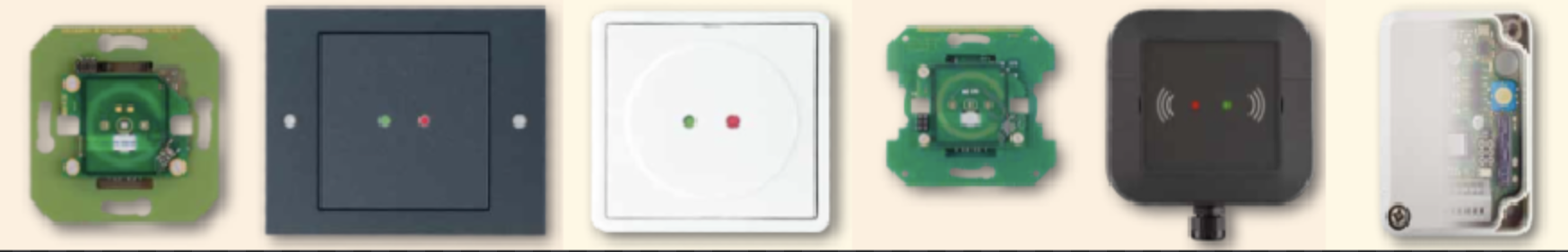
UZ WALL READERS
-
CX 2132 - wall reader
-
CX 2134 - Wall reader, external version
-
Optional: CX 6930 - safety relay module
-
Optional: CX 6830 - wall reader housing
Required tools & accessories
- Uhlmann & Zacher wall reader in original packaging
- Optional: Uhlmann & Zacher safety relay module in original packaging
- Optional: Uhlmann & Zacher wall reader housing in original packaging
- Uhlmann & Zacher Servicekey card
- Optional: Uhlmann & Zacher battery replacement and dismantling card
- BlueID Lock Admin App, including tenant name, user name and password
- BlueID ACaaS Web GUI, including tenant name, user name and password
- Phase checker
Mechanical assembly & electrical installation
The technical data on dimensions, power supply, operating temperature, installation location and more can be found in the respective product data sheet.
CX 2132 Data sheet
CX 2134 Data sheet
CX 6930 Data sheet
CX 6830 Data sheet
Uhlmann & Zacher, CX6130, Clex prime, wall reader, short operating instructions, version: 1.0
Uhlmann & Zacher, CX6930, Safety relay module, installation and operating instructions, version: 1.0
1. Observe the manufacturer's instructions for intended use as well as the safety and warning information.
Short operating instructions, “1 General”, p. 3f
2. Familiarize yourself with the pin assignment of the wall reader. Contacts 1 + 2 are used for the operating voltage (supply voltage 8-24 V DC or 8-16 V AC, power consumption 1 W, max. 5 W). Contacts 9 + 10 serve as main closer relays for switching electronic door openers, electric locks, electronic door and gate drives.
Short operating instructions, “4 Terminal assignment”, p. 6
3. Optional: Familiarize yourself with the pin assignment of the safety relay module. Contacts 11 + 12 of the safety relay module must be connected to contacts 15 + 16 of the wall reader (RS485 A on RS485 online bus A, RS485 B on RS485 online bus B).
Installation and operating instructions, “Terminal assignment of the SRM”, p. 5
4. Prepare the installation on site.
Short operating instructions, “5.1 Preparing the installation”, p. 7
5. Connect the wall reader according to the connection assignment.
Short operating instructions, “5.3 Connection”, p. 8
6. Optional: Connect the safety relay module according to the terminal assignment. Connect the wall reader to the safety relay module according to the connection assignments.
Installation and operating instructions, “Functional description of the safety relay module (SRM)”, p. 4
7. Install the wall reader.
Short operating instructions, “5.4 Installation”, p. 9
8. Optional: install the safety relay module.
Installation
1. Get acquainted to the Uhlmann & Zacher Servicekey card.
2. Set the time with the help of the BlueID Lock Admin App.
3. Create a new lock in the ACaaS Web GUI.
4. After the lock has now been created in the Access GUI, the wall reader is now assigned with the Lock Admin App.
5. Optional: Perform the “pairing” between the wall reader and the safety relay module. To do this, insert the learning plug into the safety module, press the “Open” button once in the Lock Admin app and then pull the learning plug out again.
6. Test functionality with the help of the Lock Admin App.